Devices for reversing neutron polarization
Crossed magnetic fields:
static field H0 and RF field Hrf
Adiabatic radiofrequency flipper (arf)
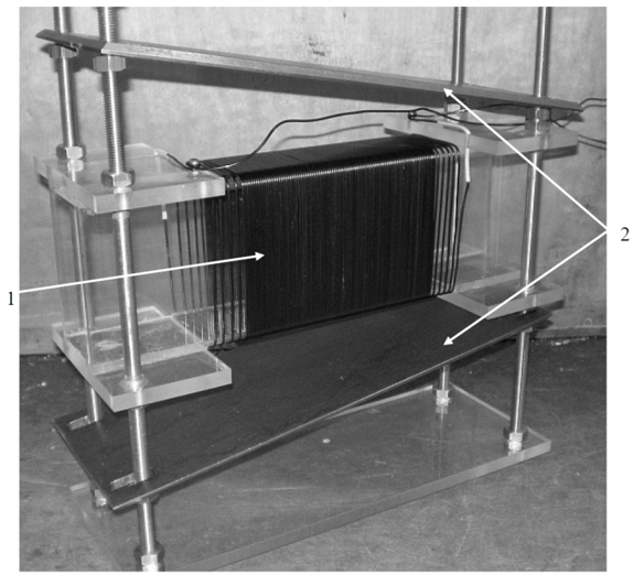
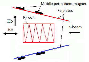
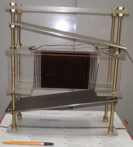
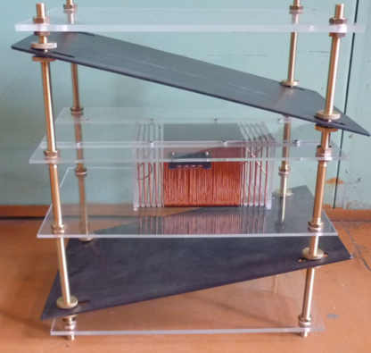
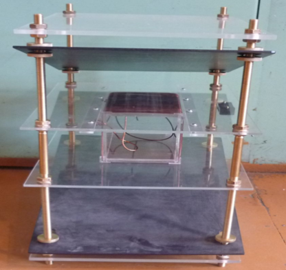
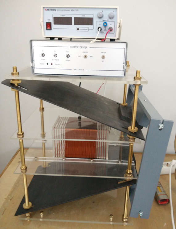
Standard flipper for thermal neutrons. 1-RF coil, 2 – Fe plates with mobile permanent magnet
Typical flipper construction for termal neutrons
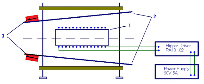
1-RF coil, 2 – Fe plates, 3 –mobile magnet
Large-cross-section resonance adiabatic flipper for scattered neutrons:
The inner entrance diameter of the flipper is 200 mm, and the exit diameter is 350 mm. Static magnetic field at the center of the flipper H0 = 25 Oe with a gradient of 40 Oe over length L = 600 mm. RF field frequency,
f = 73 kHz, and amplitude value of the RF field H1 = 25 Oe.. Flipping efficiency P = 0.998 ± 0.002 over, the whole flipper cross section. The described version of the flipper has a large aperture (±9°) for the scattered beam of the small-angle setup
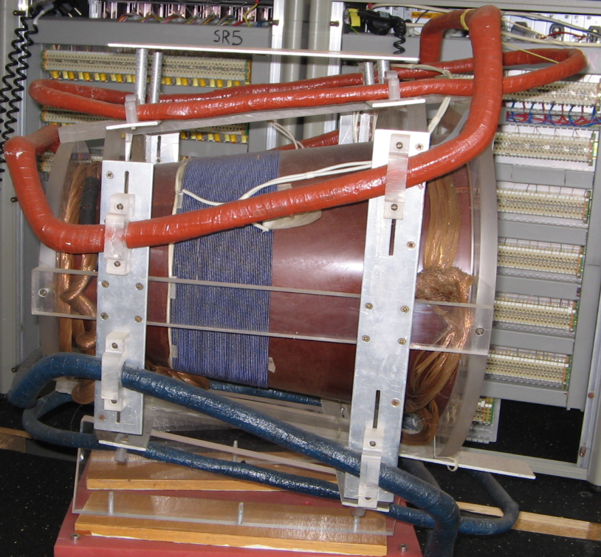
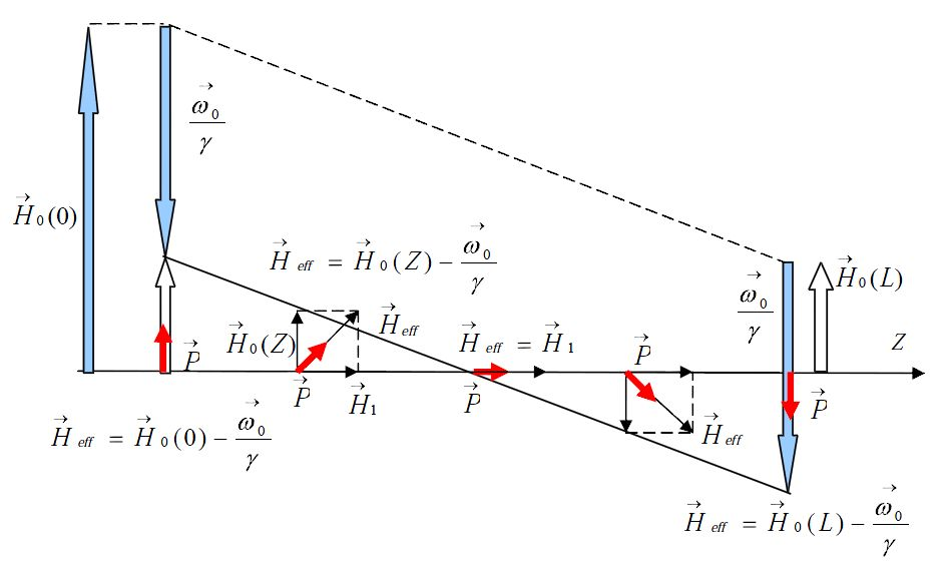
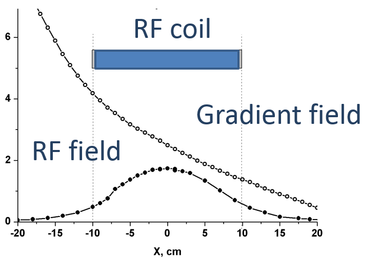
Diagram of the magnetic fields of the ARF
in the coordinate system rotating with frequency
ω0. Spin adiabatically turns in effective field
Hef = H0-ω0/γ in permanent gradient guide field Ho
Large cross-section resonance AFR for scattered neutrons:
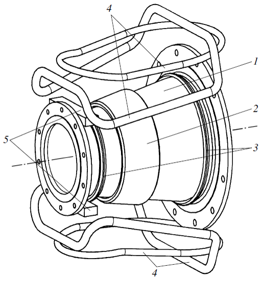
(1) plastic conical casing, (2) solenoidal coil generating RF field H1, (3) copper ring for spatial limitation of RF field H1, (4) coils generating static gradient field H0, and (5) correcting permanent magnets for mating with the guiding magnetic field of the facility [8].
Flipper electronic equipment
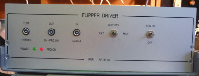
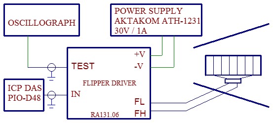
Flipper driver (RF autonomous generator), Imax=8A, Fmax=150kHz
Flipper problems
There is no problem to make flippers for location it at free air space. As a rule, neutron beams incident on a sample are collimated well, and production of a similar flipper for them causes no difficulties. The matter becomes complicated when a flipper must be mounted on a neutron guide. Problems arise when the neutron guide is itself located in vacuum space. The issue is that a high RF voltage (1–2 kV) is applied to The RF coils to create required field H1, and residual gas in a crude vacuum becomes ionized, which causes the RF generator output to be short-circuited. In addition, it is difficult to remove heat from the RF coils in vacuum.
First variant to solve both problems
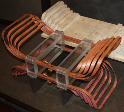
Advantages: the low voltage V=100 -150 V (no ionisation) and sufficient heat sink
Disadvantages: very high RF current (near 60-70 Am) and no electroisolation
ARF coils for a neutron guide in the vacuum space
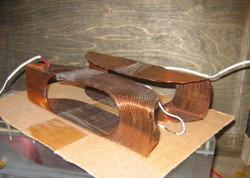
Advantages over Helmholtz coils:
1.RF coils can be easily installed and rearranged on the neutron guide.
2. Low inductance and therefore lowvoltage.
3 Low loss
